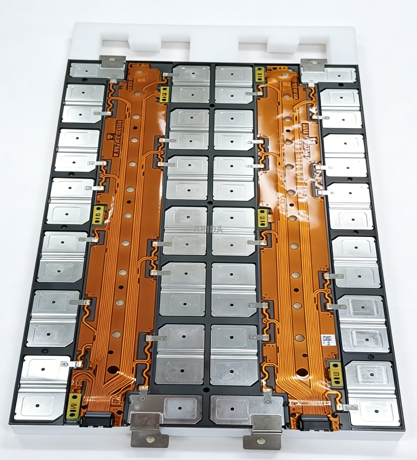
EV battery pack design carries immense engineering stakes today. Misaligned tolerances or inadequate current-carrying capacity in a cell connection system (CCS) directly causes severe thermal risks. They also trigger massive assembly bottlenecks on the production line. To prevent these failures, battery engineers and manufacturing partners must bridge their technical communication gap. We wrote this guide to detail the exact data you need to design, quote, and produce a reliable solution.
By providing comprehensive initial specifications, you reduce unnecessary prototyping iterations. You also minimize expensive upfront tooling costs and significantly accelerate your time-to-market. You will learn the specific electrical, mechanical, and material data points required to move your project from concept to scalable production smoothly.
Key Takeaways
Designing a Custom CCS Integrated Busbar requires precise data across four pillars: electrical loads, mechanical constraints, sensor integration, and material grades.
Clarifying the choice between FPC (Flexible Printed Circuit) and traditional wire harnesses early dictates the manufacturing process and tooling requirements.
Submitting complete 3D CAD models, routing diagrams, and compliance requirements (e.g., UL, ISO) is critical for accurate manufacturer evaluation and shortlisting.
Why Exact Specifications Matter for a Custom CCS Integrated Busbar
The Risk of Assumption
Vague specifications inevitably lead to dangerous tolerance stack-up issues. When you assume standard dimensions, small deviations multiply across the battery module. This risks placing severe mechanical stress on individual battery cells during vehicle operation. Cell terminal fatigue is a common failure point in performance applications. You must clearly define every dimensional boundary to prevent these microscopic shifts from causing catastrophic fractures.
Tooling and Lead Time Implications
Manufacturing a Custom CCS Integrated Busbar requires heavy upfront investment. Custom stamping dies and FPC tooling demand significant capital and fabrication time. Revisions forced by incomplete initial data inflate these costs exponentially. If you alter the terminal pitch after cutting the steel dies, you lose weeks of lead time. Exact data secures your production timeline and protects your initial tooling budget.
Thermal and Safety Baseline
The CCS functions as both a high-power conductive path and a delicate safety monitor. Missing peak current data directly undermines your thermal runaway prevention strategies. If the busbar cannot handle transient power spikes, it generates internal heat. This localized heating compromises the structural integrity of the surrounding insulation. Precise electrical specifications form your primary defense against thermal propagation.
1. Electrical Performance and Cell Configuration Data
Cell Chemistry and Topology
Your manufacturer needs to know your exact battery type. Cylindrical, prismatic, and pouch cells all demand entirely different connection architectures. You must specify the exact series-parallel configuration. A 16S1P topology requires different conductor sizing and routing than a 4S2P setup. Cell chemistry also dictates expected operating voltage curves.
LFP (Lithium Iron Phosphate): Lower nominal voltage requires specific current handling.
NMC (Nickel Manganese Cobalt): Higher energy density demands aggressive thermal monitoring.
Electrical load defines the fundamental geometry of the busbar. You must provide clear numbers for continuous operating current. We also need to know the peak transient current and its exact duration. A 500-ampere spike lasting two seconds requires different thermal mass than a ten-second spike. You must also supply the maximum system voltage. Engineers use this peak voltage to calculate mandatory creepage and clearance distances based on global safety standards.
Impedance Limits
You must establish acceptable resistance thresholds across the entire conductor network. A poorly specified CCS Integrated BusbarBattery Module Busbar experiences excessive joule heating during rapid charging cycles. Setting strict impedance limits prevents this localized heating. It also ensures consistent power delivery and improves the overall efficiency of your energy storage system.
2. Mechanical Layout and Spatial Constraints
Dimensional Boundaries
Space is the ultimate premium inside any modern battery enclosure. You must define the absolute maximum length, width, and height limitations. The CCS must fit seamlessly within the battery module housing without rubbing against the top cover. Even a millimeter of interference can wear through dielectric films over years of road vibration.
Cell Spacing and Pitch
Provide exact center-to-center distances between all cell terminals. You must include acceptable dimensional tolerances. Standard modules often specify a pitch tolerance of ±0.1mm. If the manufactured busbar pitch does not perfectly match the welded cells, assembly teams must force the alignment. This forced alignment creates immediate stress at the weld joints.
Vibration and Shock Requirements
The expected operating environment heavily dictates mechanical design. Automotive applications endure brutal multi-axis vibration. Stationary energy storage systems face minimal movement but require long-term creep resistance. You must specify the intended environment. This data determines whether the design requires deep stress-relief features, flexible expansion joints, or rigid structural supports.
Connection Methods
Your choice of joining technology impacts the surface plating and physical shape of the contact tabs. You must specify your intended assembly method upfront.
Comparison of Cell Terminal Connection Techniques
The table below summarizes common methods used for module assembly.
Connection Method
Primary Advantage
Design Requirement for CCS
Laser Welding
Low heat input, high precision
Requires highly flat contact surfaces and compatible plating (e.g., Nickel).
Ultrasonic Welding
Excellent for dissimilar metals
Requires sufficient tab area for the sonotrode tool to grip securely.
Wire Bonding
Built-in fusing for cell-level safety
Requires specialized bond pads and extreme surface cleanliness.
Bolted Connections
Easy maintenance and field repair
Requires integrated anti-rotation features and torque specification limits.
3. Sensor Integration and Signal Routing
FPC vs. Wire Harness
You must clearly state your required data acquisition method. FPCs save valuable space and reduce overall weight. They do require highly specific routing data and significant tooling investment. Conversely, wire harnesses offer greater physical flexibility and lower initial tooling costs. You must still define their securing points clearly to prevent chafing against the module chassis.
Voltage Sampling Points
Provide the exact locations and total quantity of voltage monitoring nodes. Every series connection typically requires a dedicated sensing trace. You must define where these traces break out from the main power path. Proper spacing prevents high-voltage arcing to adjacent low-voltage sensor lines.
Temperature Monitoring (NTC)
Thermal management relies on accurate temperature data. You must specify the number of NTC thermistors required. Identify target placement locations across the assembly. Engineers typically place these sensors near the hottest anticipated cells or the main positive terminal. You must also specify the preferred bonding method. Surface-mount soldering, epoxy potting, and mechanical riveting each offer different thermal response times.
Connector Specifications
The interface linking the CCS to the Battery Management System (BMS) requires strict definition. Specify your preferred connector brand and model. Include the required pin pitch and the exact pinout configuration. Providing this connector data early ensures the FPC tail or harness breakout matches the BMS receptacle perfectly.
4. Material Selection and Insulation Standards
Conductor Materials
Your choice of base metal defines both weight and electrical efficiency. Specify your clear preferences. Copper (e.g., T2 or C11000 grade) offers maximum electrical conductivity but adds significant weight. Aluminum (e.g., 1060 or 1070 grade) provides massive weight reduction but requires larger cross-sectional areas to match copper's current capacity. You must explicitly state the required material thickness.
Surface Plating
Raw copper oxidizes rapidly, and bare aluminum creates insulating oxide layers. You must dictate surface plating requirements to prevent this degradation. Nickel plating is standard for laser welding applications. Tin plating offers excellent corrosion resistance for general-purpose environments. Silver plating maximizes conductivity at high-current mechanical joints. Choose the plating that matches your assembly method.
Insulation and Dielectric Requirements
We need your specific preferences for protective materials. Common choices include PET film, PI (Polyimide) film, or powder-based epoxy coatings.
Material Grade: PI film withstands extreme heat but costs more than PET.
Dielectric Strength: Specify the required withstand voltage. A common automotive standard is 3000V DC for 1 minute without leakage.
Flammability Rating: Safety compliance almost universally requires a UL94 V-0 rating to prevent fire propagation.
5. Prototyping, Compliance, and Shortlisting a Manufacturer
Required Deliverables for RFQ
Submitting a vague email guarantees a vague quotation. You must consolidate your requirements into standard file formats. Provide STEP or IGES files for 3D mechanical models. Supply standard Gerber files for any FPC layouts. Always include detailed 2D PDF drawings annotated with Geometric Dimensioning and Tolerancing (GD&T) rules. These deliverables give manufacturers the exact geometry they need to quote accurately.
Compliance and Certification Lenses
You must verify the manufacturer's ability to meet rigorous automotive standards. Ask for their specific certifications. IATF 16949 ensures strict quality control in automotive supply chains. ISO 26262 functional safety compliance is non-negotiable for critical electrical components. You should also confirm their products meet global environmental standards like RoHS and REACH.
Design for Manufacturability (DFM)
Evaluate vendors based on their upfront engineering capabilities. The best partners conduct a rigorous DFM review before cutting any physical tools. They run thermal simulations to validate current density and heat dissipation across the proposed busbar geometry. This proactive simulation ensures your design is genuinely scalable for mass production.
Conclusion
Customizing a highly reliable cell connection system remains a deeply collaborative engineering effort. It is never a simple off-the-shelf purchase. The success of your battery pack depends entirely on the precision of the data you provide to your manufacturing partner.
We encourage engineering teams and procurement officers to consolidate their requirements thoroughly. Gather all your electrical loads, mechanical boundaries, and sensory layouts into one unified technical document. Do this before approaching any supplier for an initial quote.
If you have your data ready, take the next crucial step. Submit your 3D CAD files and technical requirements to a trusted manufacturing partner today. A rigorous DFM review and an accurate initial project quotation will keep your production schedule on track.
FAQ
Q: What is the standard lead time for a Custom CCS Integrated Busbar prototype?
A: Lead times vary based on the required manufacturing process. Rapid prototyping using laser cutting and soft tooling usually takes 2 to 4 weeks. If the design requires hard stamping dies and custom FPC lamination tools, the initial lead time extends to 6 or 8 weeks. Providing exact CAD files upfront minimizes delays.
Q: Can I change the FPC layout after the initial tooling is complete?
A: Yes, but it incurs significant penalties. Altering FPC traces post-tooling requires new etching masks and cutting dies. This completely invalidates your previous tooling investment. It also delays production by several weeks. You must finalize voltage nodes and sensor routing before approving the final tooling phase.
Q: Does a Battery Module Busbar require thermal simulation before manufacturing?
A: Yes, thermal modeling is an absolute necessity. Simulations validate current density hotspots and overall heat dissipation under peak loads. Running these models digitally identifies dangerous bottlenecks before cutting metal. This proactive step reduces physical iteration cycles and prevents catastrophic melting during extreme fast-charging events.