Standard nickel strips often force battery pack designers into inefficient layouts. This limitation becomes obvious during complex builds. High-discharge applications like e-bikes, electric skateboards, and custom energy storage systems demand non-standard cell spacing. Off-the-shelf rolls limit design flexibility and restrict thermal performance heavily.
Moving from generic rolls to customized tabs requires careful engineering. You must balance strict electrical requirements against thermal management limitations. Assembly constraints also dictate your final design choices. A poor connection ruins an otherwise perfectly balanced battery pack. You must engineer these connections precisely to prevent dangerous localized hotspots.
This guide breaks down the engineering criteria for designing tailored battery connections. We explore ampacity needs, layout geometries, and spot welding realities. You will learn how to specify materials accurately for your next project. Procuring properly dimensioned tabs ensures safety and peak performance across your entire energy storage system.
Key Takeaways
- Custom Shaped Interconnects eliminate the structural and electrical bottlenecks of standard ladder or staggered roll strips.
- Evaluating tab thickness vs. width is critical: maximizing width for a specific cell spacing often provides better thermal dissipation than simply stacking standard strips.
- Custom tooling requires upfront CAD planning, but significantly reduces spot welding failure rates during high-volume pack assembly.
- Validating material purity (99.6%+ pure nickel) is essential, as plated steel alternatives introduce severe resistance and corrosion risks in high-draw scenarios.
The Engineering Challenge: When Standard Spacing Restricts Pack Design
Standard 18650 and 21700 nickel rolls assume linear, uniform cell holders. These generic rolls force engineers into rigid, straight-line layouts. High-density pack designs frequently require offset, honeycomb, or curved structures. Custom enclosures rarely accommodate perfect rectangles. You must adapt the battery geometry to fit specific enclosure spaces smoothly. Generic strips fail completely in these scenarios. They cannot navigate irregular angles safely.
Using generic strips for irregular spacing introduces severe engineering compromises. You physically stress the spot welds by bending straight strips into angled paths. Installers often overlap generic strips to bridge awkward gaps. Overlapping increases electrical resistance significantly. It also increases overall pack height unnecessarily. This overlapping causes uneven current distribution across your parallel groups. Uneven current draw degrades specific cells faster than others. Your entire pack suffers premature capacity loss.
A successful custom interconnect must bridge variable gaps effortlessly. It must avoid mechanical tension entirely across the joints. The material must carry the required continuous and peak current. It must stay safely within thermal limits during maximum discharge events. Finally, the strip must sit perfectly flush against every cell terminal. Flush seating allows automated or manual spot welding to succeed consistently. Any air gap between the terminal and the metal guarantees a failed weld.
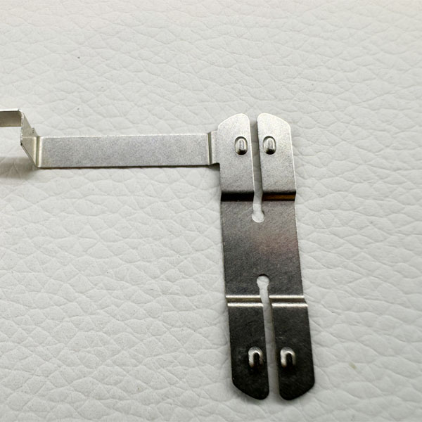
Custom Shaped Interconnects: Design Approaches for Variable Spacing
Design approaches for variable spacing fall into two distinct solution categories. You must choose the right manufacturing method based on your production volume. Stamping suits high-volume assembly lines perfectly. Manufacturers create custom dies for specific multi-cell layouts. You might design a 4P or 6P staggered block die. Stamping works best when cell spacing remains permanently locked. Tooling costs are high upfront. However, per-unit costs drop dramatically during mass production.
Laser and waterjet cutting serve a different purpose entirely. These cutting methods dominate the prototyping phase. They require zero tooling costs. You can test thermal constraints quickly. You can verify physical fitment on new battery enclosures directly. This step prevents expensive stamping die errors later. Engineering teams rely on these fast-turnaround methods for iterative testing.
Layout Geometries
Layout geometries require careful spatial planning. Offset and honeycomb routing maximizes energy density securely. You design angled bridges to accommodate nested cylindrical cells. This technique minimizes dead space inside the enclosure.
- Honeycomb Routing: Nests cells tightly together. It reduces overall pack footprint. It demands precise angular cuts on the connection bridges.
- Offset Routing: Shifts parallel groups slightly. It fits cells into triangular or curved frames safely.
Slotted bridges add another layer of mechanical reliability. You incorporate custom relief slits between cell connections. These pre-cut slits guide welding current properly through the cell casing. They prevent the current from traveling across the top surface. Slotted bridges also allow slight flex during pack expansion. Battery cells swell slightly during charge cycles. Pure Nickel TabsCustom Shaped Interconnects absorb this minimal movement gracefully without tearing the spot welds.
Dimensioning for Ampacity: Thickness, Width, and the Layering Dilemma
Matching physical space to electrical demand requires precise calculations. You must evaluate thickness and width simultaneously. Tight cell spacing limits your maximum bridge width strictly. Increasing tab width becomes physically impossible in dense honeycomb packs. You must increase thickness instead to carry the required amperage. Moving from 0.15mm to 0.2mm or 0.3mm changes your assembly process completely. Thicker materials impact spot welder capability directly.
The single versus double layer debate arises frequently among pack builders. Thick single layers provide lower electrical resistance. They offer superior thermal mass distribution. However, they require powerful industrial spot welders. The welder must penetrate the thick nickel entirely. It must avoid excessive heat buildup at the delicate cell terminal.
Builders often stack double layers as a temporary workaround. They do this when their equipment cannot weld thick Custom Pure Nickel Tabs directly. Transparency about this practice is vital. Double-layering introduces severe structural risks. You face invisible cold welds between the stacked layers. Micro-arcing occurs silently beneath the top strip during high-current draw. Single-layer custom tabs remain the superior engineering choice. Optimized bridge widths manage current safely.
Ampacity Configuration Comparison
Single vs Double Layer Tab Configurations | Feature | Single Layer (Thick) | Double Layer (Stacked) |
| Electrical Resistance | Minimal (Continuous path) | Higher (Contact resistance between layers) |
| Thermal Dissipation | Excellent uniform cooling | Poor (Trapped heat between layers) |
| Spot Welder Requirement | High-Joule Industrial Welder | Standard Hobbyist Welder |
| Micro-Arcing Risk | None | High (Under high peak loads) |
| Mechanical Stability | High structural integrity | Prone to delamination under flex |
Assembly Realities: Spot Welding and Mechanical Stress
Custom geometries only work well if attached reliably. Spot welding pure nickel poses distinct physical challenges. Nickel-plated steel welds easily due to high electrical resistance. Pure nickel conducts electricity highly efficiently instead. This high conductivity demands significantly more energy to generate localized heat. The welder must create a proper weld nugget instantly. Custom designs must account for your specific welder limitations. You cannot specify 0.3mm material if your welder caps at 0.15mm capacity.
Vibration introduces another massive failure point. Rigid joints tear under continuous high vibration. Electric skateboards experience brutal road impacts daily. E-bikes absorb constant high-frequency chatter. Design mitigation saves the battery pack from catastrophic failure.
- Assess the vibration profile: Determine the maximum physical shock your enclosure will endure.
- Add stress-relief curves: Modify the CAD file to include rounded S-bends.
- Position the bends properly: Place these curves in the bridge segment between distant cells.
- Test the flex point: Ensure bending happens at the S-curve rather than the weld point.
These S-bends absorb kinetic energy safely. They allow the metal to flex infinitesimally. This intentional flexibility protects the brittle spot welds. It isolates terminal connections from mechanical strain completely.
Prototyping to Production: Specifying Your Custom Pure Nickel Tabs
Evaluating a supplier requires strict shortlisting logic. You must verify material purity first. Ensure the supplier provides proper material test reports (MTRs). These documents must guarantee 99.6% purity minimum (N6/N4 grade). You should perform secondary verification independently. Salt-water tests reveal rust on plated steel within days. Grinding tests show distinct spark patterns. Pure metal produces almost no sparks. Plated steel throws bright, showering sparks immediately.
CAD preparation demands exact dimensioning. Prepare strictly toleranced DXF or STEP files. Specify tolerances for slot widths explicitly. Center-to-center hole spacing must match your cell holders exactly. Injection-molded holders vary slightly between different manufacturing batches. You must measure your actual physical holders before finalizing the CAD drawing.
Actionable next steps ensure project success. Request a small batch of laser-cut prototypes first. Use these initial prototypes for resistance testing. Tune your spot weld parameters perfectly on dummy cells. Confirm the bridge width manages your peak discharge current safely. Complete these validation steps thoroughly before commissioning expensive stamping dies.
Conclusion
Transitioning to tailored layouts marks a critical maturation point for battery pack manufacturing. You stop forcing generic parts to fit complex enclosures. You shift focus directly toward optimizing thermal and electrical efficiency. Matching interconnect geometry exactly to your cell spacing eliminates structural weak points. It reduces overall assembly time drastically on the production floor.
Engineered shapes distribute continuous current evenly across every parallel group. This precision extends the total lifecycle of your battery system. It prevents premature cell degradation caused by localized hotspots. Contact a material engineering specialist today. Submit your CAD designs to evaluate tooling costs and lead times. Optimize your next high-discharge pack properly from the ground up.
FAQ
Q: What is the minimum order quantity (MOQ) typically required for custom shaped interconnects?
A: Laser-cut prototypes usually require no MOQ or a very low minimum (e.g., 50 pieces). They carry zero tooling fees. Stamped production runs require significant upfront tooling fees. Stamping manufacturers typically set MOQs between 5,000 and 10,000 pieces to offset die creation costs.
Q: How do I calculate the correct bridge width for my specific cell spacing?
A: Use standard ampacity charts for pure metal. Calculate the exact cross-sectional area by multiplying thickness by width. Factor in your peak versus continuous discharge rates. Ensure the calculated area supports your maximum continuous current without exceeding a 10°C temperature rise.
Q: Can custom tabs be designed with pre-cut slots for easier spot welding?
A: Yes. Adding center slits forces the welding current down through the battery casing. It prevents current from taking the path of least resistance across the top surface. This design modification heavily improves weld quality and penetration on thicker materials.
Q: How can I verify my custom tabs are pure nickel and not nickel-plated steel?
A: Perform a spark test using a rotary grinder. Pure material produces almost zero sparks. Plated steel throws bright, long sparks. Alternatively, submerge a scratched sample in saltwater for 48 hours. Plated steel rusts quickly, while pure metal remains completely unchanged.