Battery chemistry strictly dictates maximum performance limits in any system. However, the interconnection network determines whether a pack consistently reaches those limits safely. Standardized cables fail constantly under extreme thermal loads. Basic stamping methods also fall short. They simply cannot survive the mechanical and spatial constraints of modern 800V+ architectures. High-cycle Energy Storage Systems (ESS) face similar operational hurdles today. You must overcome these exact bottlenecks to scale effectively.
Sourcing reliable OEM Battery Busbar Solutions requires evaluating electrical conductivity meticulously. You must also measure mechanical vibration tolerance and verify dielectric resilience. Long-term chemical compatibility matters immensely during the design phase. Readers will learn how to align busbar designs with specific cell formats accurately. We will explore advanced structural selections for harsh physical environments. You will also discover the assembly advantages of integrated cell contact systems.
Key Takeaways
Application Dictates Design: Busbar architecture must align strictly with battery chemistry (e.g., NCM vs. LFP) and cell form factor (prismatic, cylindrical, or pouch).
Integration Drives Efficiency: Transitioning to CCS (Cells Contact System) integrated busbars reduces pack volume and enables non-destructive cell monitoring.
Resilience Over Baseline Specs: True system reliability in EVs and ESS relies on multi-layer flexible structures and high-temperature coatings (e.g., PI/PFA) to resist vibration fatigue and thermal degradation.
Vendor Viability: A qualified OEM partner must demonstrate a clear path from Design for Manufacturability (DFM) and prototype validation to automated, high-yield mass production.
The Business & Engineering Stakes in High-Voltage Architectures
Engineers face a massive bottleneck when scaling high-power battery packs. They must balance power density perfectly against strict thermal runaway prevention. High-voltage systems push traditional current distribution components beyond natural physical limits. Heavy-duty ESS grids demand robust power delivery mechanisms constantly.
Inadequate busbar selection causes severe cascading failures across the module. Localized heating initiates rapidly at poorly specified contact points. This heat increases internal resistance almost instantly. Higher resistance generates even more heat. Catastrophic electrical shorting eventually destroys the entire module. You lose expensive hardware quickly. You compromise user safety completely.
Flat, defined-geometry busbars easily replace flexible wiring harnesses. They offer significantly improved heat dissipation across wide surface areas. They maintain a consistently lower inductance profile across the active circuit. They optimize critical space inside compact enclosures effectively. You gain better thermal regulation instantly. You secure long-term structural stability. Modern pack designs eliminate loose cables entirely. They rely on rigid paths to handle massive current spikes safely.
Aligning Busbar Design with Battery Chemistry and Cell Formats
Battery chemistry dictates your specific interconnection strategy. Ternary Lithium (NCM/NCA) batteries are highly sensitive to charging efficiency. Fast-charging 800V platforms require ultra-low resistance materials. You need high-purity oxygen-free copper. Thick silver plating further reduces contact resistance at terminal joints. Robust dielectric shielding protects components against high-voltage arcs. You must manage extreme temperature spikes during ultra-fast DC charging cycles.
Lithium Iron Phosphate (LFP) batteries serve an entirely different purpose. They endure high cycle life and sustained continuous currents. You must prioritize solutions preventing long-term metal creep. Vibration loosening presents a major threat to LFP modules over decades of use. Specific torque management protocols prevent this gradual degradation. Copper-aluminum composite structures help balance performance expectations against manufacturing budgets.
We must also map busbar designs directly to cell form factors. Prismatic cells require rigid structural backbones. These thick backbones manage extreme current loads effortlessly. They dissipate heat effectively away from the core. Cylindrical and pouch cells need adaptable ESS busbar connector modules. Compact interconnection arrays maximize volumetric power density in these tight layouts.
| Battery Chemistry / Format | Primary Performance Focus | Optimal Interconnect Strategy |
| Ternary Lithium (NCM/NCA) | High peak power, extreme fast charging. | Oxygen-free copper, thick silver plating, max dielectric shielding. |
| Lithium Iron Phosphate (LFP) | Sustained current, long cycle life, cost control. | Copper-aluminum composites, anti-creep structures, rigid joints. |
| Prismatic Cells | High structural stability, massive heat output. | Thick rigid backbones, active cooling integration. |
| Cylindrical / Pouch Cells | Volumetric density, variable spatial layouts. | Adaptable connectors, multi-point laser welded arrays. |
Material and Structural Selection for Harsh Environments
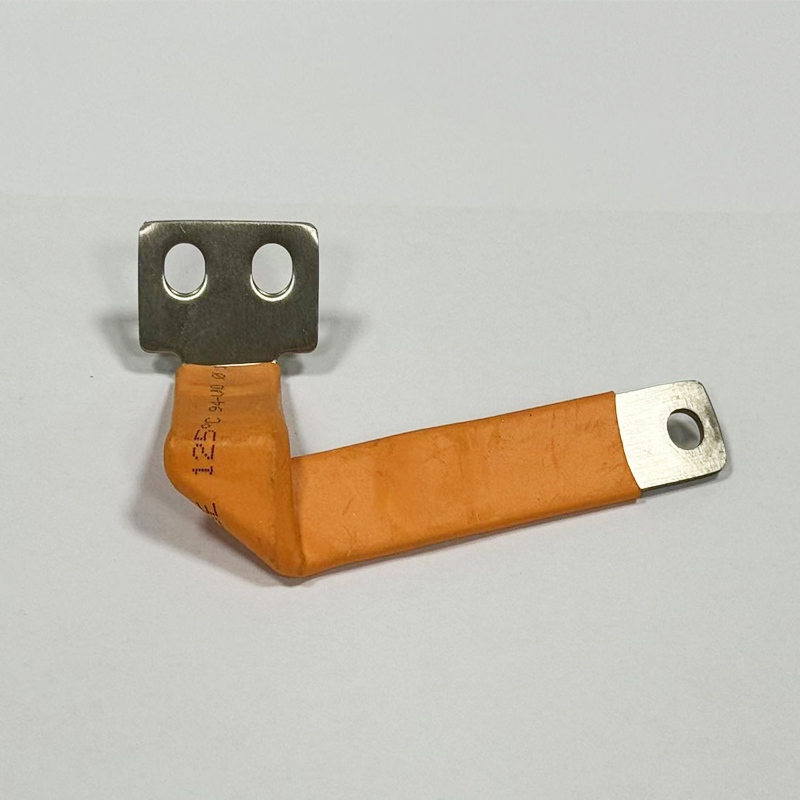
Physical operational environments dictate strict material limits. Contrast a rigid stamping piece against a flexible copper busbar. Rigid parts transfer physical shock directly to delicate cell terminals. They crack under sustained mechanical stress. A multi-layer laminated structure absorbs this physical shock smoothly. Engineers use diffusion welding to bond dozens of thin copper foils together. This flexibility compensates for continuous heat cycling. Mobile applications rely on this elasticity for survival. Off-highway equipment demands vibration-proof interconnects.
Dielectric and high-temperature protection define overall system safety. Modern automotive architectures require 3000V+ isolation securely. UL94-V-0 flame retardancy is non-negotiable for strict automotive compliance. Specialized coatings prevent high-voltage breakdown effectively. PI (Polyimide) films, PFA layers, and epoxy resins isolate active conductors. They maintain stability at temperatures peaking at 150°C. Powertrain engineers prefer powder-coated epoxy for complex 3D bends. Film wrapping works best for straight, flexible spans. You must specify the correct coating based on spatial clearance.
Space Optimization with a CCS Integrated Busbar
Solution categories evolve rapidly in the EV sector. A CCS (Cells Contact System) acts as more than a simple power conductor. It functions as a critical sub-component of the sophisticated Battery Management System (BMS).
Integrating data acquisition streamlines the entire module layout. You combine voltage and temperature sensors directly alongside the EV battery busbar. This smart integration reduces manual assembly steps drastically. It cuts overall pack weight significantly. Automation becomes seamless.
Engineers evaluate multiple signal collection substrates carefully. We list the most prominent variants below:
FPC (Flexible Printed Circuit): Delivers ultra-light, highly stable signal routing. Best for premium automotive applications despite higher initial tooling costs.
FFC (Flexible Flat Cable): Provides extremely cost-efficient, continuous connectivity. Ideal for long-module mass production runs in stationary storage.
FDC (Flexible Die-cut Circuit): Reduces intermediate processing steps. Suitable for highly automated, high-volume manufacturing lines.
A modern CCS integrated busbar array transforms routine pack maintenance. It facilitates non-destructive testing seamlessly. Technicians perform precision module diagnostics safely. They monitor individual cell health without initiating full pack teardowns. This accessibility lowers warranty service times immensely.
Implementation Realities: Mitigating Long-Term Lifecycle Risks
Operational wear and tear degrades interconnections silently over time. Systems undergo 4,000+ ESS cycles or 100,000 EV miles. Physical components experience relentless fatigue under these conditions.
Thermal cycling causes severe micro-loosening at primary contact points. Metals expand during peak charging and contract while resting. This phenomenon leads directly to torque loss. Looser connections instantly increase localized resistance. Moisture and dust ingress compromise dielectric barriers eventually. Insulation degradation accelerates electrical tracking risks.
Engineering countermeasures secure the lifecycle span effectively. We highly recommend implementing these standard protections:
Implement robust elastic compensation designs to absorb expansion stresses.
Apply strict anti-creep fastening protocols during automated module assembly.
Utilize anti-corrosion tin or thick nickel plating on all exposed terminals.
Deploy Belleville washers to maintain constant pressure across bolted joints.
These best practices prevent catastrophic failures reliably. Common mistakes include ignoring thermal expansion calculations during early prototyping. You must account for dimensional changes early in the design phase.
Shortlisting an OEM Manufacturing Partner for Custom Battery Busbars
Vendor evaluation criteria must transition from basic product features to total supply chain reliability. A basic prototyping shop cannot scale like a Tier-1 capable supplier. You need a trusted, technically advanced partner.
A credible manufacturer provides a transparent project lifecycle roadmap constantly. The rigorous validation process guarantees manufacturing success.
R&D and DFM: Early design intervention balances pack weight, thermal limits, and tooling budgets.
Validation (VAL) and Pilot: First Article Inspection (FAI) ensures exact specification compliance. Extreme-environment reliability testing verifies maximum performance limits.
Mass Production: Automated assembly guarantees batch consistency. Strict IQC, IPQC, and OQC loops maintain high monthly yield capacities.
Look for verifiable automotive and industrial certifications always. IATF 16949 and ISO 9001 demonstrate rigorous quality management systems. RoHS and REACH compliance indicate responsible, safe material sourcing. Every custom battery busbar must meet these stringent international standards. Never compromise on vendor auditing procedures.
Conclusion
The right busbar acts as the defining safety boundary for advanced battery systems. It dictates electrical efficiency limits across the entire platform. Proper component selection prevents catastrophic thermal failures effectively.
Procurement and engineering teams should shift away from commoditized component purchasing. Focus strictly on co-engineered, application-specific interconnect solutions instead. This strategic shift ensures superior lifecycle performance and module reliability.
Submit your pack schematics or thermal constraints to our expert engineering team today. We provide a comprehensive DFM review for your architecture. Schedule a customized prototyping consultation immediately to accelerate your production timeline.
FAQ
Q: What is the difference between a standard rigid busbar and a flexible busbar in battery packs?
A: A rigid busbar provides a solid structural backbone, ideal for stationary packs with minimal movement. A flexible busbar utilizes multi-layer laminated copper foils to absorb physical vibration. This flexibility tolerates continuous thermal expansion and contraction, preventing structural fatigue in dynamic EV and off-highway applications.
Q: How does an integrated CCS busbar improve battery manufacturing?
A: It combines power distribution and data acquisition into a single module. This reduces total component count and pack weight. It perfectly aligns BMS sensors for automated assembly lines, lowering production times and minimizing manual wiring errors.
Q: What insulation materials are required for 800V EV battery architectures?
A: High-voltage architectures demand robust dielectric options capable of handling extreme thermal loads. Manufacturers typically use PI (Polyimide) or PFA films, alongside specialized epoxy coatings. These materials offer 3000V+ isolation and withstand temperature peaks up to 150°C without breaking down.
Q: What is the typical lead time for a custom OEM battery busbar prototype?
A: Lead times vary based on design complexity. Typical B2B timelines range from 2 to 4 weeks. This includes initial Design for Manufacturability (DFM) sign-off, custom tooling preparation, and the final delivery of the First Article Inspection (FAI) prototype.